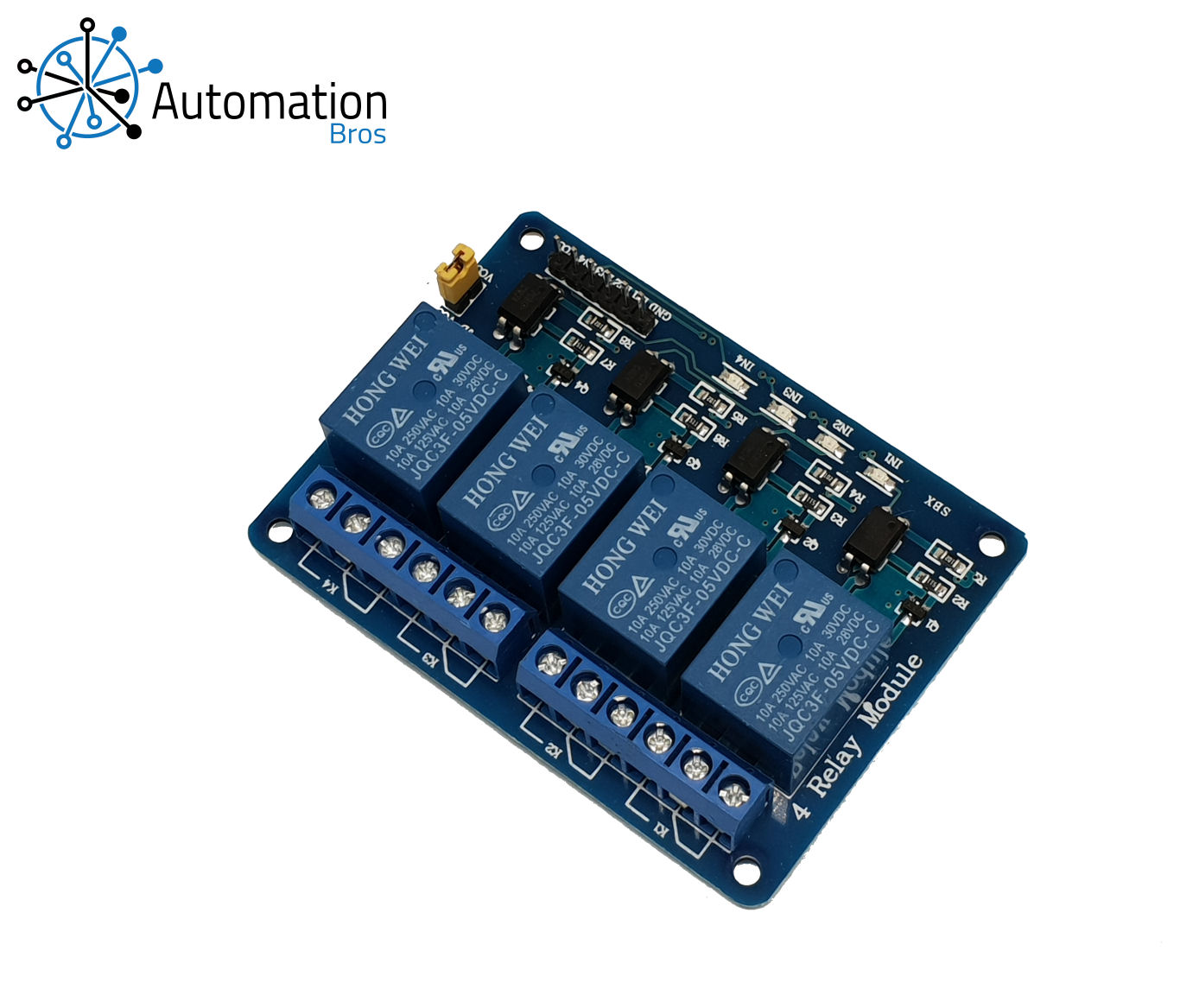
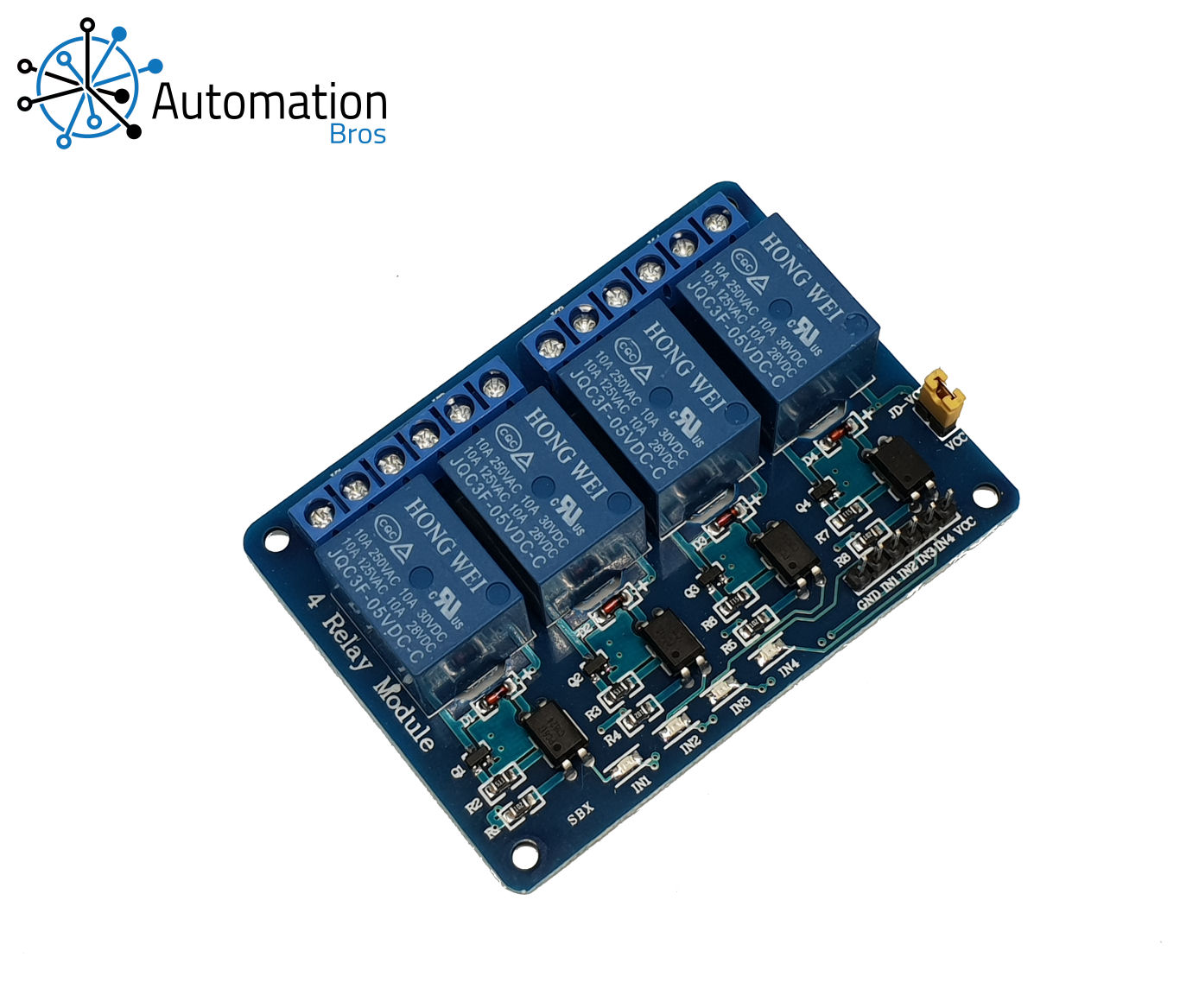
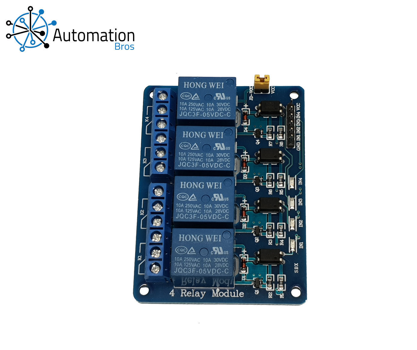
5V Relay 4 Channel
4 Channel Relay Module This is a 5v, 10A 4-Channel Relay interface board. It can be used to control various appliances, and other equipment with large current. Individual LEDs to indicate which Relays are on. It can be controlled directly with 3.3v or 5v logic signals from a micro-controller or TTL drivers.
- Code
- Questions & Answers
- Specifications
basic Arduino Code for 4 Channel Relay Module
The Arduino LED (connected to pin 13) will flash briefly to indicate Relay 1 is ON, at the same time Relay 1 will turn ON. After a brief interval (aproximatley 1/3 second) the led will flash again, at the same time Relay 2 will turn ON. The same will happen for relays 3 & 4. About 1 second later, all four relays will turn OFF for about 1 second and the cycle will repeat. If you open the Serial Port at 9600 Baud: You will see a text confirmation of when a Relay is ON or OFF You will also see the TX Led flash briefly when the serial lines are sent.
/* BASIC 4 RELAY TIMER
 ***************************************************
 * WIRING:
 * 5v pin on the Arduino to VCC on the relay board
 * GND pin on the Arduino to GND on the relay board
 * Pin 4 on the Arduino to IN1 on the relay board
 * Pin 5 on the Arduino to IN2 on the relay board
 * Pin 6 on the Arduino to IN3 on the relay board
 * Pin 7 on the Arduino to IN4 on the relay board
 ***************************************************
 * FUNCTION:
 * The Arduino LED (connected to pin 13) will flash breifly
 * to indicate Relay 1 is ON, at the same time Relay 1 will turn ON.
 * After a breif  interval (aproximatley 1/3 second) the led will flash again,
 * At the same time Relay 2 will turn ON.
 * The same will happen for relays 3 & 4.
 *
 * About 1 second later, all four relays will turn OFF
 * for about 1 second and the cycle will repeat.
 *
 * If you open the Serial Port at 9600 Baud:
 * You will see a text confirmation of when a Relay is ON or OFF
 * You will also see the TX Led flash breifly when the serial lines are sent.
 */

// Declare Pins
int firstRelay = 4;
int secondRelay = 5;
int thirdRelay = 6;
int fourthRelay = 7;
int ledPin = 13;

// the setup function runs once when you press reset or power the board
void setup() {
  // Open a Serial port at 9600 Baud
  Serial.begin(9600);
  // Initialize digital pins 4, 5, 6, 7, & 13 as outputs.
  pinMode(firstRelay, OUTPUT);
  pinMode(secondRelay, OUTPUT);
  pinMode(thirdRelay, OUTPUT);
  pinMode(fourthRelay, OUTPUT);
  pinMode(ledPin, OUTPUT);
  // Write digital pins 4, 5, 6 & 7 HIGH to hold the relays off.
  digitalWrite(firstRelay, HIGH);
  digitalWrite(secondRelay, HIGH);
  digitalWrite(thirdRelay, HIGH);
  digitalWrite(fourthRelay, HIGH);
}

// The loop runs over and over again until the arduino is re-programmed
void loop() {
  digitalWrite(ledPin, HIGH);   // The LED is On
  digitalWrite(firstRelay, LOW);   // Relay 1 is On
  Serial.println("Relay 1 is ON");
  delay(350);                       // Led delay
  digitalWrite(ledPin, LOW);  // The LED is Off
  delay(350);                       // Led delay
  digitalWrite(ledPin, HIGH);   // The LED is On
  digitalWrite(secondRelay, LOW);   // Relay 2 is On
  Serial.println("Relay 2 is ON");
  delay(350);                       // Led delay
  digitalWrite(ledPin, LOW);  // The LED is Off
  delay(350);                       // Led delay
  digitalWrite(ledPin, HIGH);   // The LED is On
  digitalWrite(thirdRelay, LOW);     // Relay 3 is On
  Serial.println("Relay 3 is ON");
  delay(350); // Led delay
  digitalWrite(ledPin, LOW);  // The LED is Off
  delay(350);                       // Led delay
  digitalWrite(ledPin, HIGH);   // The LED is On
  digitalWrite(fourthRelay, LOW);  // Relay 4 is On
  Serial.println("Relay 4 is ON");
  delay(350); // Led delay
  digitalWrite(ledPin, LOW);  // The LED is Off
  delay(650);                 // Relay interval
  digitalWrite(firstRelay, HIGH);   // Relay 1 is Off
  digitalWrite(secondRelay, HIGH);   // Relay 2 is Off
  digitalWrite(thirdRelay, HIGH);   // Relay 3 is Off
  digitalWrite(fourthRelay, HIGH);   // Relay 4 is Off
  Serial.println("ALL Relays are OFF");
  Serial.println(""); // Add an empty line
  delay(1000);                       // wait for a second
}
intermediate Arduino Code for 4 Channel Relay Module
FUNCTION: The Arduino LED (connected to pin 13) will flash briefly when a Relay is ON. Open the Serial monitor (9600 baud) Type 1 to turn relay 1 ON Type 2 to turn relay 2 ON Type 3 to turn relay 3 ON Type 4 to turn relay 4 ON Type 0 to turn ALL Relays OFF If you open the Serial Port at 9600 Baud: You will see a text confirmation of when a relay is ON / OFF You will also see the TX Led flash briefly when the serial lines are sent.
/* INTERMEDIATE 4 RELAY PROGRAM
 ***************************************************
   WIRING:
   5v pin on the Arduino to VCC on the relay board
   GND pin on the Arduino to GND on the relay board
   Pin 4 on the Arduino to IN1 on the relay board
   Pin 5 on the Arduino to IN2 on the relay board
   Pin 6 on the Arduino to IN3 on the relay board
   Pin 7 on the Arduino to IN4 on the relay board
 ***************************************************
   FUNCTION:
   The Arduino LED (connected to pin 13)
   will flash briefly when a Relay is ON.

   Open the Serial monitor (9600 baud)
   Type 1 to turn relay 1 ON
   Type 2 to turn relay 2 ON
   Type 3 to turn relay 3 ON
   Type 4 to turn relay 4 ON
   Type 0 to turn ALL Relays OFF

   You will see a text confirmation of when a relay is ON / OFF
   You will also see the TX Led flash briefly when the serial lines are sent.
*/


// Declare Pins
int firstRelay = 4;
int secondRelay = 5;
int thirdRelay = 6;
int fourthRelay = 7;
int ledPin = 13;

void setup() {
  // Start Serial at 9600 baud
  Serial.begin(9600);

  // Set the relayPin as an OUTPUT
  pinMode(firstRelay, OUTPUT);
  pinMode(secondRelay, OUTPUT);
  pinMode(thirdRelay, OUTPUT);
  pinMode(fourthRelay, OUTPUT);
  pinMode(ledPin, OUTPUT);

  // Write digital pins 6 and 7 HIGH to hold the relays off.
  digitalWrite(firstRelay, HIGH);
  digitalWrite(secondRelay, HIGH);
  digitalWrite(thirdRelay, HIGH);
  digitalWrite(fourthRelay, HIGH);

  // Acknowledge the program
  Serial.println("PROGRAM READY");
  Serial.println(""); // Print a blank line
}

// The loop runs over and over again until the arduino is re-programmed
void loop() {
  while (Serial.available()) {
    char inChar = (char)Serial.read();
    if (inChar == '1') {
      digitalWrite(firstRelay, LOW); // Turn Relay 1 ON
      digitalWrite(ledPin, HIGH);   // The LED is On
      Serial.println("RELAY 1 is ON");
      delay(350);                       // Led delay
      digitalWrite(ledPin, LOW);  // The LED is Off
    }
    else if (inChar == '2') {
      digitalWrite(secondRelay, LOW); // Turn Relay 2 ON
      Serial.println("RELAY 2 is ON");
      digitalWrite(ledPin, HIGH);   // The LED is On
      Serial.println("RELAY 2 is ON");
      delay(350);                       // Led delay
      digitalWrite(ledPin, LOW);  // The LED is Off
    }
    else if (inChar == '3') {
      digitalWrite(thirdRelay, LOW); // Turn Relay 3 ON
      Serial.println("RELAY 3 is ON");
      digitalWrite(ledPin, HIGH);   // The LED is On
      Serial.println("RELAY 3 is ON");
      delay(350);                       // Led delay
      digitalWrite(ledPin, LOW);  // The LED is Off
    }
    else if (inChar == '4') {
      digitalWrite(fourthRelay, LOW); // Turn Relay 4 ON
      Serial.println("RELAY 4 is ON");
      digitalWrite(ledPin, HIGH);   // The LED is On
      Serial.println("RELAY 4 is ON");
      delay(350);                       // Led delay
      digitalWrite(ledPin, LOW);  // The LED is Off
    }
    else if (inChar == '0') {
      digitalWrite(firstRelay, HIGH); // Turn Relay 1 OFF
      digitalWrite(secondRelay, HIGH); // Turn Relay 2 OFF
      digitalWrite(thirdRelay, HIGH); // Turn Relay 3 OFF
      digitalWrite(fourthRelay, HIGH); // Turn Relay 4 OFF
      Serial.println("ALL RELAYS OFF");
      Serial.println("");  // Print a blank line.
    }
    else if (inChar != 1 && inChar != 2 && inChar != 3 && inChar != 4 && inChar != 0) {
      Serial.println ("Command not recognised");
      Serial.println("");  // Print a blank line.
    }
  }
}
5V Relay 4 Channel
4 CHANNEL RELAY MODULE This relay module is active low. Active Low Low = On / Less than 1 volt at the IN pin will turn the relay ON High = Off / Greater than 3 volts at the IN pin will turn the relay OFF 6 Pins: VCC / GND / IN1 / IN2 / IN3 / IN4 (Connection instructions are in the comments at the top of the example code). This Module can be controlled directly with 3.3V or 5V logic signals from a micro-controller or TTL drivers.


